
Page 1057 - Softbound_Edition_19_de
P. 1057
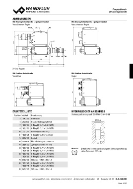
ABMESSUNGEN                                                                                                                        Proportional-DDrruuPccrkkorreepggoeertllivvoeennnattlii-ll

Mit Analog-Schnittstelle, 12-poliger Stecker                                                       Mit Analog-Schnittstelle, 7-poliger Stecker
                                                                                                   Verstärker und Regler
Verstärker und Regler
                                                                                                                                                      X2
                                   25,30 20,21                          40                                                           X1

                                                      X2                                                                             X4
                                   X1

100.4                              X4 s30                                                          118.4

                                                                            M22x1.5

                 15                                                                  (3) (2)

       35  MD= 5.5Nm                                                                          (1)         35

                        12         17                               18      50 70 60 90 80

                          MD= 5Nm    135.4                   78.4                        61
                                                         95
X4 (nur Regler)
                                                             196.4

Mit Feldbus-Schnittstelle                                                                          Mit Feldbus-Schnittstelle
Verstärker                                                                                         Regler

100.4                                                X2                                            118.4                                              X2
                                   X1                                                                                             X1

                                   X3                                                                                             X3

                                                                                                                                  X4

       35                                                                                                 35

ERSATZTEILLISTE                                                                                    HYDRAULISCHER ANSCHLUSS

Position   Artikel                 Bezeichnung                                                     Senkungszeichnung nach ISO 7789–22–04–0–98
       12  154.2700                Griffmutter
       15  253.8000                Handnotbetätigung HB4,5                                                                                              M22x1.5
       17  160.2187                O-Ring ID 18,72 x 2,62 (NBR)
       18  160.2170                O-Ring ID 17,17 x 1,78 (NBR)                                                                                                           (3)
       20  223.1317                Blindstopfen M16 x 1,5
       21  160.6131                O-Ring ID 13,00 x 1,5 (FKM)                                                                                                            (2)
       25  062.0102                Deckel
       30  072.0021                Flachdichtung 33,2 x 59,9 x 2                                                                                                          (1)
       40  208.0100                Zylinderschraube M4 x 10                                                                                                 (1)

           50 160.2188             O-Ring ID 18,77 x 1,78 (NBR)                                    Hinweis! Detaillierte Senkungszeichnung und Senkungswerkzeug
                160.6188           O-Ring ID 18,77 x 1,78 (FKM)                                                  siehe Datenblatt 2.13-1004

           60 160.2156             O-Ring ID 15,60 x 1,78 (NBR)
                160.6156           O-Ring ID 15,60 x 1,78 (FKM)

           70 049.3196             Stützring rd 16,1 x 19 x 1,4

           80 160.2140 O-Ring ID 14,00 x 1,78 (NBR)
                160.6141 O-Ring ID 14,00 x 1,78 (FKM)

           90 049.3176 Stützring rd 14,1 x 17 x 1,4

                                   www.wandfluh.com Abbildung unverbindlich Änderungen vorbehalten 5/6 Ausgabe: 20 22 2.3-643D
                                                                                                                                                                                    Seite 1057