Page 845 - Softbound_Edition_19_de
P. 845

SSppeeiicchheerrllaaddeevveennttiill

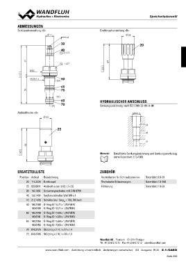
ABMESSUNGEN                                                   Drehknopfverstellung «D»

Schlüsselverstellung «S»                                                                         26

                          17         s4

                              30                                                                     20
                              40

                                    s13

117                                                s27        125
      61                                                            69
               Ø30                3(X) 50
56              M22x1.5                65
                                       75
Abdeckhaube «A»                                               HYDRAULISCHER ANSCHLUSS
                                      2(T)
                                                              Senkungszeichnung nach ISO 7789–22–06–0–98
                                       60
                             1(P) 70                                                                              M22x1.5

                         23                                                                                                           (3)
                                                                                                                                      (2)
                              25
                                                                                                                                      (1)
120                                                                                                                   (1)
      64
                                                              Hinweis! Detaillierte Senkungszeichnung und Senkungswerkzeug
                                                                            siehe Datenblatt 2.13-1006

ERSATZTEILLISTE                                               ZUBEHÖR

Position   Artikel       Bezeichnung                           Verstellarten für Schraubpatronen         Datenblatt 2.0-50
       20                                                      Technische Erläuterungen                  Datenblatt 1.0-100
       25  114.2224      Drehknopf                             Filtrierung                               Datenblatt 1.0-50
       30
       40  032.0611      Abdeckhaube rd 23 / 3 x 35
       45
       50  193.1061      Sicherungsscheibe rd 6 DIN 6799

       60  153.1402      Sechskantmutter 0,5d M8 x 1

       65  212.1488      Scheibe (nur für pN = 100, 160 bar)
                         O-Ring ID 18,77 x 1,78 (NBR)
       70  160.2188      O-Ring ID 18,77 x 1,78 (FKM)
       75  160.6188
                         O-Ring ID 14,00 x 1,78 (NBR)
           160.2140      O-Ring ID 14,00 x 1,78 (FKM)
           160.6141
                         O-Ring ID 15,60 x 1,78 (NBR)
           160.2156      O-Ring ID 15,60 x 1,78 (FKM)
           160.6156
                         Stützring rd 14,1 x 17 x 1,4
           049.3176
                         Stützring rd 16,1 x 19 x 1,4
           049.3196

                                                              Wandfluh AG Postfach CH-3714 Frutigen
                                                              Tel. +41 33 672 72 72 Fax +41 33 672 72 12 sales@wandfluh.com

                         www.wandfluh.com Abbildung unverbindlich Änderungen vorbehalten 3/3 Ausgabe: 19 24 2.1-548D
                                                                                                                                                                           Seite 845
   840   841   842   843   844   845   846   847   848   849   850