Page 926 - Softbound_Edition_19_de
P. 926

DDruruckcrkergegelevlevnentitleil

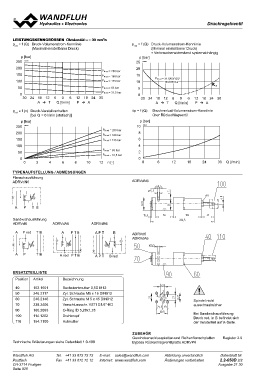
LEISTUNGSKENNGRÖSSEN Ölviskosität υ = 30 mm22/s                                   pred = f (Q) Druck-Volumenstrom-Kennlinie
pred = f (Q) Druck-Volumenstrom-Kennlinie                                                         (Minimal einstellbarer Druck)
                                                                                                  ∗ Verbraucherwiderstand systemabhängig
                (Maximal einstellbarer Druck)
                                                                                        p [bar]
    p [bar]                                                                          25 K0522
250 K0523
                                                   PN red = 200 bar               20
200                                                PN red = 160 bar
                                                   PN red = 125 bar               15
150
                                                      PN red = 63 bar                                  PN red = 31.5/63/125/           ∗
100                                                   PN red = 31,5 bar
                                                                                  10 160/200 bar
 50                                                30                              5

   0                               12 18 24                                       0
     30 24 18 12 6 0 6             PA                                              30 24 18 12 6 0 6 12 18 24 30
                  A  T Q [l/min]                                                               A  T Q [l/min] P  A

pred = f (n) Druck-Verstellverhalten                           PN red = 200 bar   ∆p = f (Q) Druckverlust-Volumenstrom-Kennlinie
               [bei Q = 0 l/min (statisch)]                    PN red = 160 bar                    über Rückschlagventil
                                                               PN red = 125 bar
       p [bar]                                                                          p [bar]
  250 K0521                                                    PN red = 63 bar       10 K0524
  200                                                          PN red = 31,5 bar
  150                                                                                  8
  100                                        10 12 n [-]
                                                                                       6
    50
      0                                                                                4
         02468
                                                                                       2

                                                                                       0
                                                                                          0 6 12 18 24 30 Q [l/min]

TYPENAUFSTELLUNG / ABMESSUNGEN                                                    ADRVdN6

Flanschausführung
ADRVdN6

A P TB

Sandwichausführung

ADRVd6              ADRVdA6                  ADRVdB6
                                                APT B
A P red T B         A PTB                                                         ADRVd6
                                                                                  ADRVdA6

AP      TB          A red P T B                    A P T B red

ERSATZTEILLISTE     Bezeichnung                                                                                               Spindel nicht
  Position Artikel                                                                                                            ausschraubsicher
                    Sechskantmutter 0,5D M12
  40 153.1601       Zyl. Schraube M5 x 16 DIN912                                                                              Bei Sandwichausführung
  50 246.2117       Zyl. Schraube M 5 x 45 DIN912                                                                             Druck red. in B befindet sich
  60 246.2146       Verschlussschr. VSTI G1/4"-ED                                                                             der Verstellteil auf A-Seite.
  70 238.2406       O-Ring ID 5,28x1,78
  90 160.2093       Drehknopf
  100 114.1202      Hutmutter
  110 154.7100

                                                                                  ZUBEHÖR                                                  Register 2.9
                                                                                  Gewindeanschlussplatten und Reihenflanschplatten
Technische Erläuterungen siehe Datenblatt 1.0-100
                                                                                  Bypass Rückschlagventilplatte ADRVP6
                                                                                        A P TB

Wandfluh AG         Tel. +41 33 672 72 72          E-mail: sales@wandfluh.com              Abbildung unverbindlich                          Datenblatt Nr.
Postfach            Fax +41 33 672 72 12           Internet: www.wandfluh.com              Änderungen vorbehalten                           2.2-650D 2/2
CH-3714 Frutigen                                                                                                                           Ausgabe 21 30
Seite 926                                                                             A P red T B                             A PTB
                                                                                                                                             APT B
   921   922   923   924   925   926   927   928   929   930   931