Page 278 - Softbound_Edition_19_de
P. 278

SScchhiieebbeerrvveennttiill

SINNBILD                            AB

Übersicht Ventile                         ab
                              a
                  AB
                                    PT
               ab                                          b
  ab
                                  AB            b AB2
                  PT                                  b
                                 a
Übersicht Kolbentypen         a                 b CB2
                                                      b
                      AB          PT
                                                b DB2
            a b AB1               AB                  b
         ab
                                    a             b EA2
                      PT      a                        b

                AB                PT            b FB2
      a b AC1                                         b
   ab                             AB
                                    a           b GB2
                PT                                    b
                              a
                AB                PT
      a b AD1
   ab                             AB

                PT                  a
                              a
            AB
                                  PT
       a    b BE1
a                 b               AB
                                    a
            PT
                              a
                AB                PT
      a b AF1
   ab                             AB
                                    a
                PT
                              a
    a       AB                    PT
a             b AG1
                     b

            PT

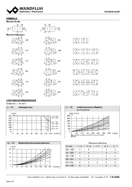
LEISTUNGSKENNGRÖSSEN

Ölviskosität u = 30 mm2/s

p = f (Q)   Leistungsgrenzen                                  QL = f (Q)  Leckölvolumenstrom-Kennlinie
                                                                          pro Steuerkante

   p [bar]                                                       Q [cm3/min]
                                                              300 K4216
350 K4215                                       AC1 / CB2
300                                             AD1 / DB2     250

250                                             AF1 / FB2     200
200                                             AG1 / GB2
150                                                           150
100                                             AB1 / AB2
                                                BE1 / EA2     100
 50
                                                               50
0                                                                                                                        350 p [bar]
   0 20 40 60 80 100 120 140 160 Q [l/min]                       0
                                                                    0 50 100 150 200 250 300

                                                                            AB1/AB2; AC1/CB2; AD1/DB2; AF1/FB2; AG1/GB2
                                                                            BEA

Δp = f (Q) Druckverlust-Volumenstrom-Kennlinie                                   Volumenstromrichtung
                                                                               P-B P-T A-T
  p [bar]                     12                              Sinnbild    P-A                                            B-T
20 K1022_1                                  3                 AB1 / AB2     5    5-3                                       2
                                            4                 AC1 / CB2     5    5-3                                       2
15                                          5                 AD1 / DB2     5    5-5                                       4
                                                              BE1 / EA2     3    313                                       2
10                                          6                 AF1 / FB2     6    665                                       4
                                                              AG1 / GB2     6    6-3                                       2
5

0
   0 20 40 60 80 100 120 140 160 Q [l/min]

                      www.wandfluh.com Abbildung unverbindlich Änderungen vorbehalten 2/3 Ausgabe: 21 22 1.5-56D

Seite 278
   273   274   275   276   277   278   279   280   281   282   283