
Page 918 - Softbound_Edition_19_de
P. 918
Ø 4,2 s19
30 DDruruckcrkergegelevlevnentitleil
25 ( 5 )
s6
8,1 38 68 32
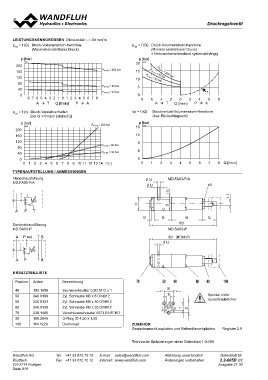
LEISTUNGSKENNGRÖSSEN Ölviskosität15υ0,1= 30 mm2/s
pred = f (Q) Druck-Volumenstrom-Kennlinie pred = f (Q) Druck-Volumenstrom-Kennlinie
(Maximal einstellbarer Druck) (Minimal einstellbarer Druck)
∗ Verbraucherwiderstand systemabhängig
150,1 (MD.SA03-P)
p [bar] Ø 4,2 p [bar]
K0011 PN red = 200 bar 20 K0012 P
200 15 PN P 8N0redba=r200 bar
10 N red = bar
160 red = 32
120
80 5
0 ∗
PN red = 80 bar 8
100 8 6420246
40 A T Q [l/min] P A
PN red = 32 bar
0
8 7 6 5704 3 2 1 0 1502 3 940 5 6 7 8 60 40
A T Q [l/min] P A
20
pred = f (n) Druck-Verstellverhalten 10 ∆p = f (Q) Druckverlust-Volumenstrom-Kennlinie
[bei Q = 0 l/min (statisch)] über Rückschlagventil
p [bar] P PN red = 200 bar p [bar]
AB 16 K0013
K0010 T To 11
21
200 30
25 ( 5 )
160 s612
120 PN red = 80 bar 8
80 PN red = 32 bar
40 4
0 0
0 1 2 3 4 5 6 7 8 9 10 11 12 13 14 n [-] 0 1 2 3 4 5 6 7 8 Q [l/min]
TYPENAUFSTELLUNG / ABMESSUNGEN Ø 7,5 MD.FA03-P/A s19
Ø 4,2
Flanschausführung
MD.FA03-P/A
A PT 8,1 38 68 32
Sandwichausführung 150,1
MD.SA03-P
MD.SA03-P
A P red T B
A PTB APT B 150,1 (MD.SA03-P)
Ø 4,2
AP TB A red P T B A P T B red
ERSATZTEILLISTE Bezeichnung 70 50 90 60 40 100
Position Artikel Sechskantmutter 0,5D M12 x 1 20 Spindel nicht
Zyl. Schraube M3 x 8 DIN912 10 ausschraubsicher
40 153.1605 Zyl. Schraube M3 x 30 DIN912
50 246.0109 Zyl. Schraube M3 x 35 DIN912 P 11
55 246.0131 Verschlussschraube VSTI G1/8"-ED AB 21
60 246.0136 O-Ring ID 4,50 x 1,50 T To
70 238.1405 Drehknopf
90 160.2045 ZUBEHÖR
100 114.1226 Gewindeanschlussplatten und Reihenflanschplatten
Register 2.9
Technische Erläuterungen siehe Datenblatt 1.0-100
Wandfluh AG Tel. +41 33 672 72 72 E-mail: sales@wandfluh.com Abbildung unverbindlich Datenblatt Nr.
Postfach Fax +41 33 672 72 12 Internet: www.wandfluh.com Änderungen vorbehalten 2.2-605D 2/2
CH-3714 Frutigen Ausgabe 21 30
Seite 918